
Page 144 - catalgo33
P. 144
dIAl IndIcAtors ApplIcAtIon specIfIcAtIon fActors
1. Regular analog styles with indicating hands are more readable
I
MecHAnIcAl dIAl ndIcAtors And AttAcHMents than digital styles when the measurements are being visually
monitored by an operator.
electronIc IndIcAtors/IndIcAtor Holders
Accurate, rugged, versatile, convenient to use and inexpensive – for 2. Select the dial size that gives you the readability you need. We
offer five regular dial sizes which will fit most applications that
these reasons and more, mechanical dial indicators with bottom
IndIca tors and GaGes Electronic indicators have an unmatched ability for the accurate 3. Choose the accuracy and readout you need – don't select a
have both space limitations and readability requirements.
plungers are the measurement workhorses of industrial production.
.0001" (or 0.001mm) readout if .001" (or 0.01mm) will do
recording of a great amount of measurement data which is used in a
your job.
variety of Statistical Process Control (SPC) operations.
4. Electronic styles are best when the measurement data needs
The first part of this section shows our complete line of mechanical/
to be collected, printed out or stored for future use.
analog dial indicators – over 180 models to give you the widest
5. Consider any special features you may need – inch or
selection in the industry. Our comparison guide, following these
millimeter reading, special shockless movement, antimagnetic,
introduction pages, has all the significant specifications to help you
make your selection.
long range, long stem, special backs, special contacts, special
holders, etc. If you don't see what you need, please contact
our Special Order Department. Even though we have a broad
line of indicators to tackle most jobs, we also do a lot of special
design, catering to the specific needs of our customers –
challenge us!
6. Starrett indicators are made to American Gage Design
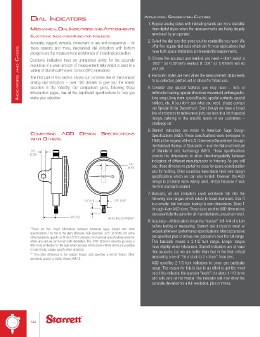
coMpArInG AGd desIGn specIfIcAtIons Specifications (AGD). These specifications were developed in
WItH otHers 1945 at the request of the U.S. Commerce Department through
the National Bureau of Standards – now the National Institute
1/4" of Standards and Technology (NIST). These specifications
(6.35) provide the dimensions to allow interchangeability between
indicators of different manufacturers in fixturing. As you will
1/4" see, these dimensions pertain to sizes for space consideration
(6.35)
and for holding. Other countries have made their own design
specifications which we can also furnish. However, the AGD
design is probably more widely used, simply because it was
the first standard created.
7. Basically, all dial indicators used worldwide fall into the
following size ranges which relate to bezel diameters. Size 0
1/4" (6.4) .375" (9.5)*
is a smaller dial indicator, having its own dimensions. Sizes 1
through 4 are AGD sizes. These sizes and the AGD dimensions
are essentially the same for all manufacturers, except as noted.
3/4" (19) #4-48 (M 2.5) THREAD**
8. Accuracy – All indicators should be "loaded" 1/8-1/4 of a turn
before testing or measuring. Starrett dial indicators meet or
*There are two major differences between American Gage Design and other exceed all known performance specifications. Most accuracies
specifications. The first is the stem diameter. AGD specifies .375" (9.5mm) and some
other standards specify an 8mm (.315") diameter. International specifications allow for are specified plus or minus one graduation over the full range.
either one and we can furnish both diameters. The .375" (9.5mm) diameter provides a This basically means a 2-1/2 turn range. Longer ranges
little more protection for the rack when clamped on the stem – 8mm stems are available have slightly wider tolerances. Starrett indicators are at least
on any model, please specify when ordering. that accurate, but we are better than that in the final critical
** The other difference is the contact thread. AGD specifies a #4-48 thread. Other measuring zone of "10 o'clock to 2 o'clock" from zero.
standards specify a metric thread, #M2.5.
AGD specifies 2-1/3 turn indicators to cover any particular
range. The reason for this is that in an effort to get the most
out of the indicator, the operator "loads" it to about 1-1/3 turns
and sets zero on his master. The indicator will now show the
accurate deviation for a full revolution, plus or minus.
144