
Page 195 - catalgo33
P. 195
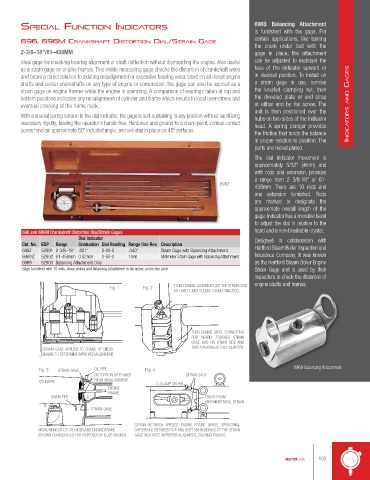
specIAl functIon IndIcAtors                                                  696B  Balancing Attachment
                                                                                     is  furnished  with the  gage. For
                                                                                     certain applications, like turning
        696, 696M crAnKsHAft dIstortIon dIAl/strAIn GAGe
                                                                                     the crank under test with the
        2-3/8–18"/61–458MM                                                           gage in place, the attachment
        Ideal gage for checking bearing alignment or shaft deflection without dismantling the engine. Also useful   can be adjusted to maintain the
        as a strain gage on engine frames. This inside measuring gage checks the distortion of crankshaft webs   face of the indicator upward or
        and bears a direct relation to existing misalignment or excessive bearing wear. Used on all diesel engine   in  desired position. To install  on
        shafts and center crankshafts on any type of engine or compressor, the gage can also be applied as a   a strain gage in use, remove
        strain gage on engine frames while the engine is operating. A comparison of readings taken at top and   the knurled clamping nut, then
        bottom positions indicates any misalignment of cylinder and frame which results in local over-stress and   the doweled plate or end strap
        eventual cracking of the frame neck.                                         at either end by the screw. The   IndIca tors and GaGes
                                                                                     unit is then positioned over the
        With a special spring tension in the dial indicator, the gage is self-sustaining in any position without sacrificing   hubs on two sides of the indicator
        necessary rigidity, leaving the operator's hands free. Hardened and ground to a sharp point, conical contact   head. A spring plunger provides
        points have an approximate 60º included angle, and will stay in place on 45º surfaces.
                                                                                     the friction that holds the balance
                                                                                     in proper relation to position. The
                                                                                     parts are nickel plated.
                                                                                     The dial indicator movement is
                                                                                     approximately 5/32" (4mm) and
                                                                                     with rods and extension, provides
                                                                                     a range from 2 3/8-18" or 61-
                                                                          696Z
                                                                                     458mm.  There are 10 rods and
                                                                                     one extension furnished. Rods
                                                                                     are marked to designate the
                                                                                     approximate overall length of the
                                                                                     gage. Indicator has a movable bezel
                                                                                     to adjust the dial in relation to the
        696 and 696M Crankshaft Distortion Dial/Strain Gages                         hand and a non-breakable crystal.
                           Dial Indicator                                            Designed in collaboration with
        Cat. No. EDP  Range  Graduation Dial Reading Range One Rev.  Description     Hartford Steam Boiler Inspection and
        696Z   52901 2-3/8–18" .001"  0-20-0  .040"   Strain Gage with Balancing Attachment
        696MZ  52902 61-458mm 0.02mm  0-50-0  1mm     Millimeter Strain Gage with Balancing Attachment  Insurance Company. It was known
        696B   52903 Balancing Attachment Only                                       as the Hartford Steam Boiler Engine
        Gage furnished with 10 rods, sharp points and balancing attachment in attractive, protective case.  Strain Gage and is used by their
                                                                                     inspectors to check the distortion of

                                     Fig. 1     Fig. 2     TO DETERMINE ALIGNMENT, SET THE STRAIN GAGE   engine shafts and frames.
                                                           SO THAT IT JUST CLEARS CONNECTING ROD.


                                                                TURN ENGINE UNTIL CONNECTING
                                                                ROD NEARLY  TOUCHES STRAIN
                                                                GAGE ROD ON OTHER SIDE  AND
               STRAIN GAGE APPLIED TO CRANK OF DIESEL           TAKE A READING AT EACH QUARTER.
               ENGINE TO DETERMINE IMPROPER ALIGNMENT.

              Fig. 3  STRAIN GAGE  OIL PIPE      Fig. 4                                           696B Balancing Attachment
                                DISTORTION OF FLANGE           STRAIN GAGE
              CYLINDER          FROM MISALIGNMENT    C-CLAMP ON RIB
                                     ENGINE
                                     FRAME
                  DRAIN PIPE  A                                      CRACK FROM
                                                                     UNSYMMETRICAL STRAIN
                B
                               STRAIN GAGE
                                              STRAIN BETWEEN  APPLIED ENGINE FRAME (WHILE OPERATING),
              MISALIGNMENT OF CYLINDER AND ENGINE FRAME  DIFFERENCE BETWEEN TOP AND BOTTOM READINGS OF THE STRAIN
              (SHOWN EXAGGERATED FOR PURPOSES OF ILLUSTRATION)  GAGE INDICATES IMPROPER ALIGNMENT, CAUSING CRACKS.


                                                                                               starrett.com  195